- #BIT SERIAL ADDER VHDL CODE HOW TO#
- #BIT SERIAL ADDER VHDL CODE SERIAL#
- #BIT SERIAL ADDER VHDL CODE UPDATE#
- #BIT SERIAL ADDER VHDL CODE FULL#
- #BIT SERIAL ADDER VHDL CODE SOFTWARE#
#BIT SERIAL ADDER VHDL CODE UPDATE#
The design shouldn't update the final result before the addition/subtraction is finished if you're wondering why I have done it the way I have. The adder block outputs (Cout and adderout) are also inputs to the module. The associated VHDL source code is included in Appendix A: VHDL Source Code. I do have signals for saturation and overflow that I am going to implement later on but they aren't really used at the moment so don't worry about them. 8-Bit Ripple Carry Adder Controller 8 reset clk START STOP Ain Bin RC MultiplierResult Multiplicand 8 16 RA RB 8 8 8 Cout Addout LSB.
#BIT SERIAL ADDER VHDL CODE HOW TO#
I've been trying to solve this problem for a few hours now and can't seem to figure out how to do it, so could you please take a look and see what I can do to fix it? Would be very much appreciated! Write a VHDL program that builds an 8-bit, full-adder circuit.
#BIT SERIAL ADDER VHDL CODE SERIAL#
I've tried to start storing the result at index_counter - 1 since the index jumps to 1 on the first clock cycle, but then I get a fatal error in the simulation. .vhdl code for 8-bit serial adder dataseet code for BCD to binary adder vhdl code for asynchronous decade counter vhdl code for dattasheet BCD adder. In the previous tutorial, VHDL Tutorial 20, we learned how to design 4-bit binary-to-gray & gray-to-binary code converters by using VHDL.

This is implemented using the standard resize function provided in the numericstd package as in line 31 and 32. Pay attention that before performing the addition operation you must extend the number of bit of the input operand. When i do simulation, the output is always zeros And some times it gives me the same number but with a shift I dont know. I am writing a VHDL code to impelemt 8 bit serial adder with accumulator. Following is the Verilog code for an unsigned 8-bit adder with carry. vhdl - 8 bit serial adder with accumulator - Stack Overflow. Following is the Verilog code for a 4-bit unsigned down counter with. Enter the code as seen below into the empty file. Ive a design problem in VHDL with a serial adder. The following is the VHDL code for the 1-bit adder. Select 'VHDL Source Code' and type in adder1in the name field, click OK.
#BIT SERIAL ADDER VHDL CODE FULL#
The problem I have is that the counter increases to 1 right away when it enters the process so that when I try to add the vectors a = 0101 0101 and b = 1010 1010 I get y = 1111 111X and the carrys = 0000 000X. In the VHDL code, the full adder is implemented in line 24 on the registered input. Double-click on 'Add New File' in the Design Browser window.
#BIT SERIAL ADDER VHDL CODE SOFTWARE#
But I obviously encounter problems since I'm probably still thinking a bit too much software programming I guess.

DSP BUILDER FOR INTEL FPGAS ADVANCED BLOCKSET.

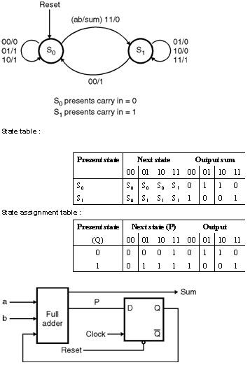
The logic behind it is very easily understood, you just have a counter for the index and so on. Vhdl Code For Serial Binary Adder Adder THE BCD ADDER VHDL PROGRAMMING CODE AND TEST BENCH. Half_adder f(input1,input2,answer,carry) įull_adder f(input1,input2,carry,answer,carry) Įndgenerate endmodule // : FPGA projects, Verilog projects, VHDL projects // Verilog project: Verilog code for N-bit Adder // Verilog code for half adder module half_adder(x,y,s,c) Įndmodule // half adder // fpga4student.I'm trying to implement a serial adder/subtractor in VHDL, I've done it the ripple carry way before but now I'm supposed to implement the same functionality by just using one full adder cell instead of N-amount of cells so I have to shift the bits from the vectors in to the full adder/subtractor and store the result in another vector which I just shift the index for as well. When i do simulation, the output is always zeros And some times it gives me the same number but with a shift I dont know what is the problem, i tried to put A,B as inout but didnt work as well. : FPGA projects, Verilog projects, VHDL projects // Verilog project: Verilog code for N-bit Adder // Top Level Verilog code for N-bit Adder using Structural Modeling module N_bit_adder(input1,input2,answer) Vhdl Vs Systemverilog I am writing a VHDL code to impelemt 8 bit serial adder with accumulator.


 0 kommentar(er)
